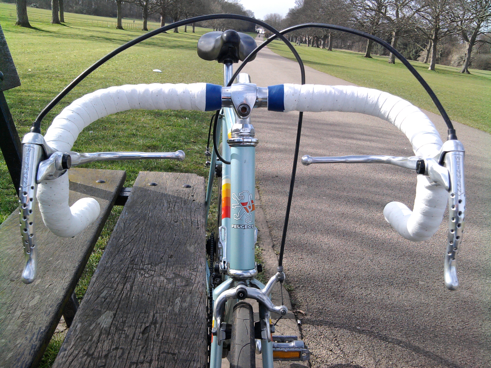
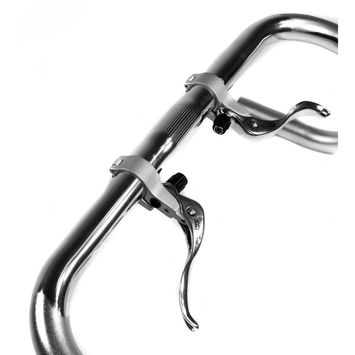
Remember how your dad’s 10-speed from the 70s/80s had an extra set of brake levers by the “tops”? They were for the top part of a drop style handlebar, like this:
Whatever the case is, I’m still fond of them and wish they were still a thing. Bike manufactures mostly solved this problem by putting ergonomic hoods on the brake levers so you can rest your hand on the top of the bar where it curves down.
Like driving with your hands at 9 & 3 the paddle shifters are easier to reach… but I can still press the brake when I’m cruising at 12 & crotch 😎 I want the same thing on my bike. I like keeping my hands on the tops when I’m relaxing, and I don’t want to do an emergency hand move if I need to stop quickly.
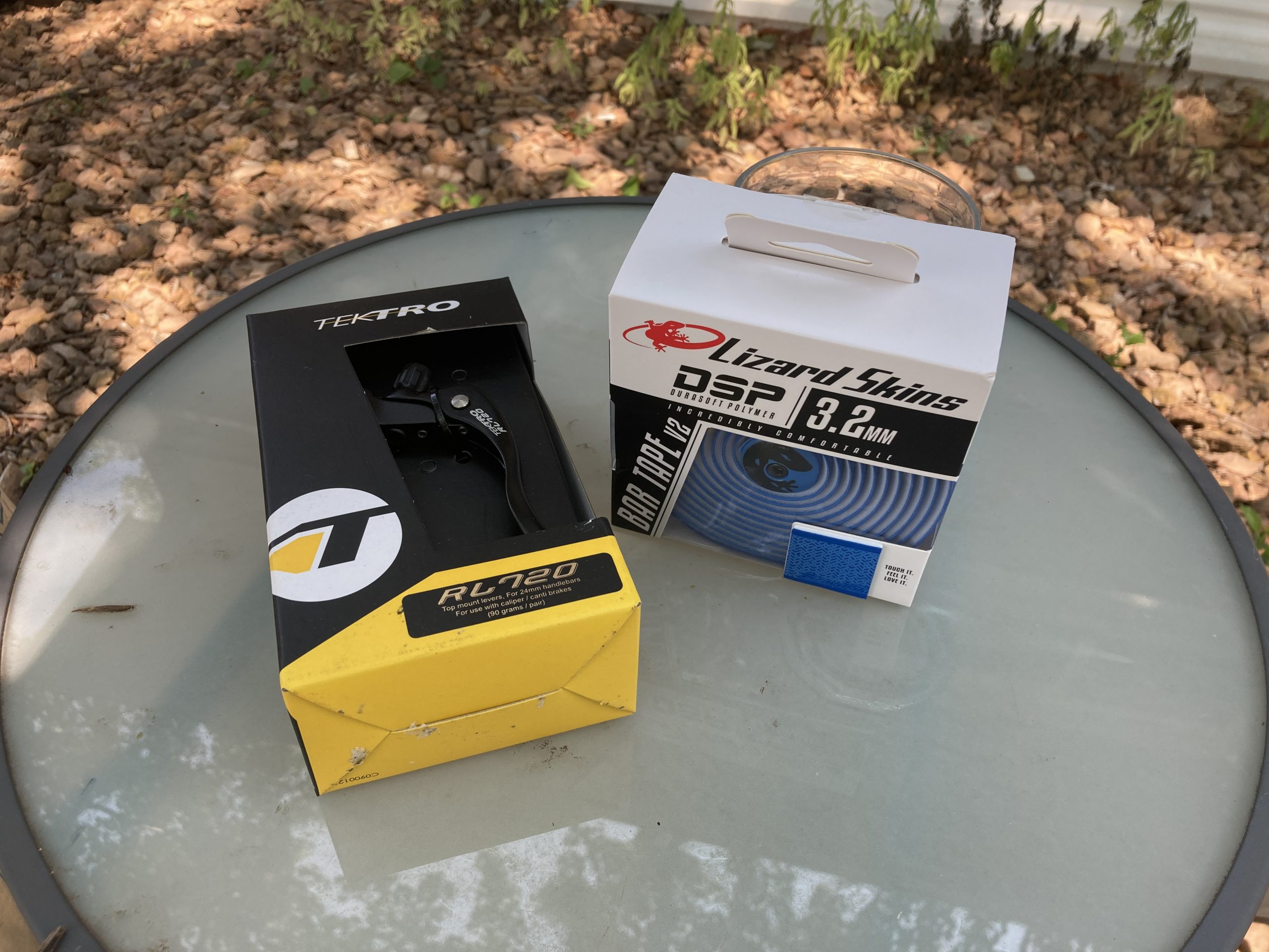
These cute little add-ons go in-line with the drop levers to provide full braking ability from the tops. When you’re adding them, you’ll need to remove and reinstall your bar tape, so I took the opportunity to get some new bar tape – went with Lizard Skins 3.2mm tape in blue to add some color.
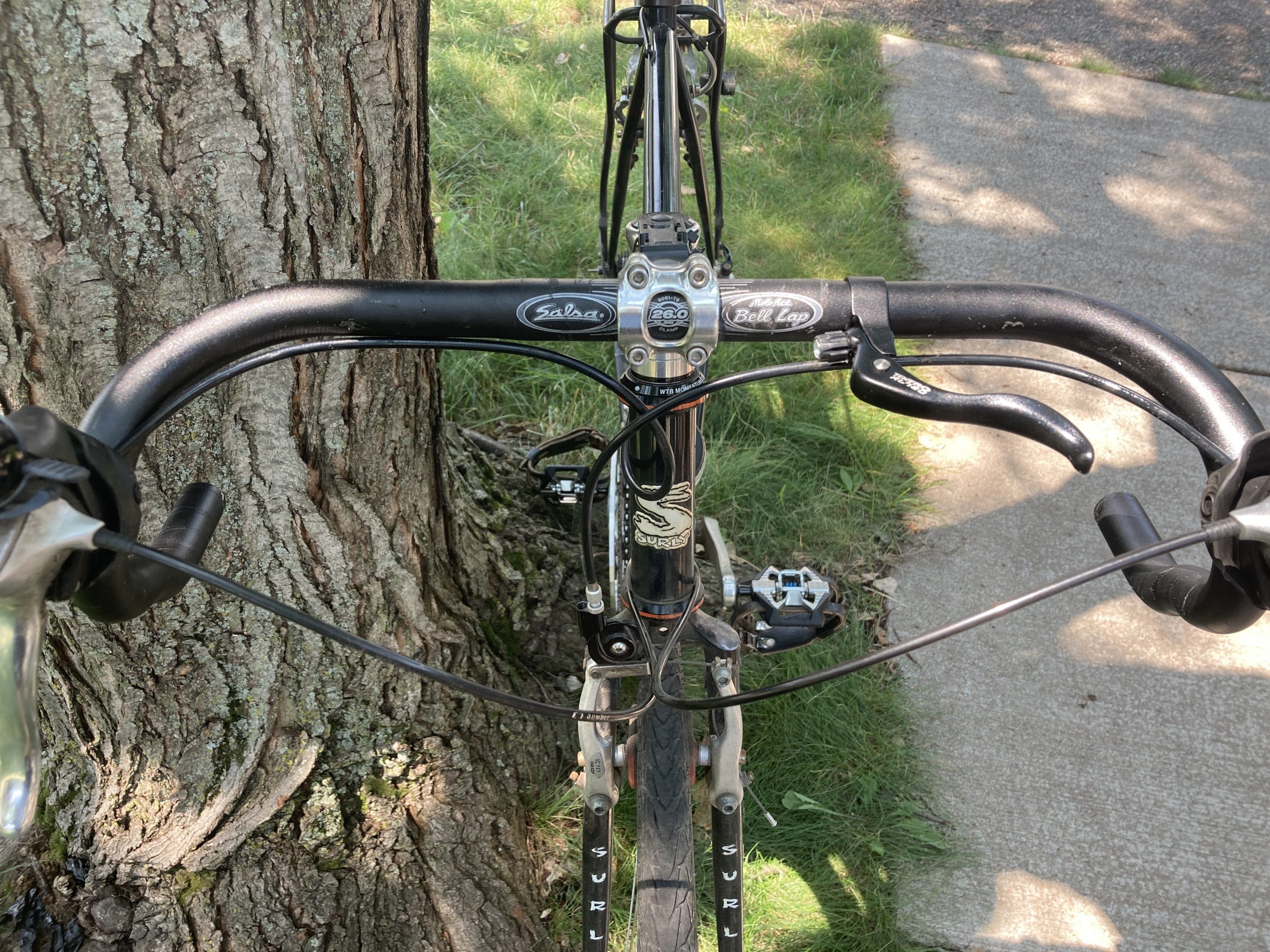
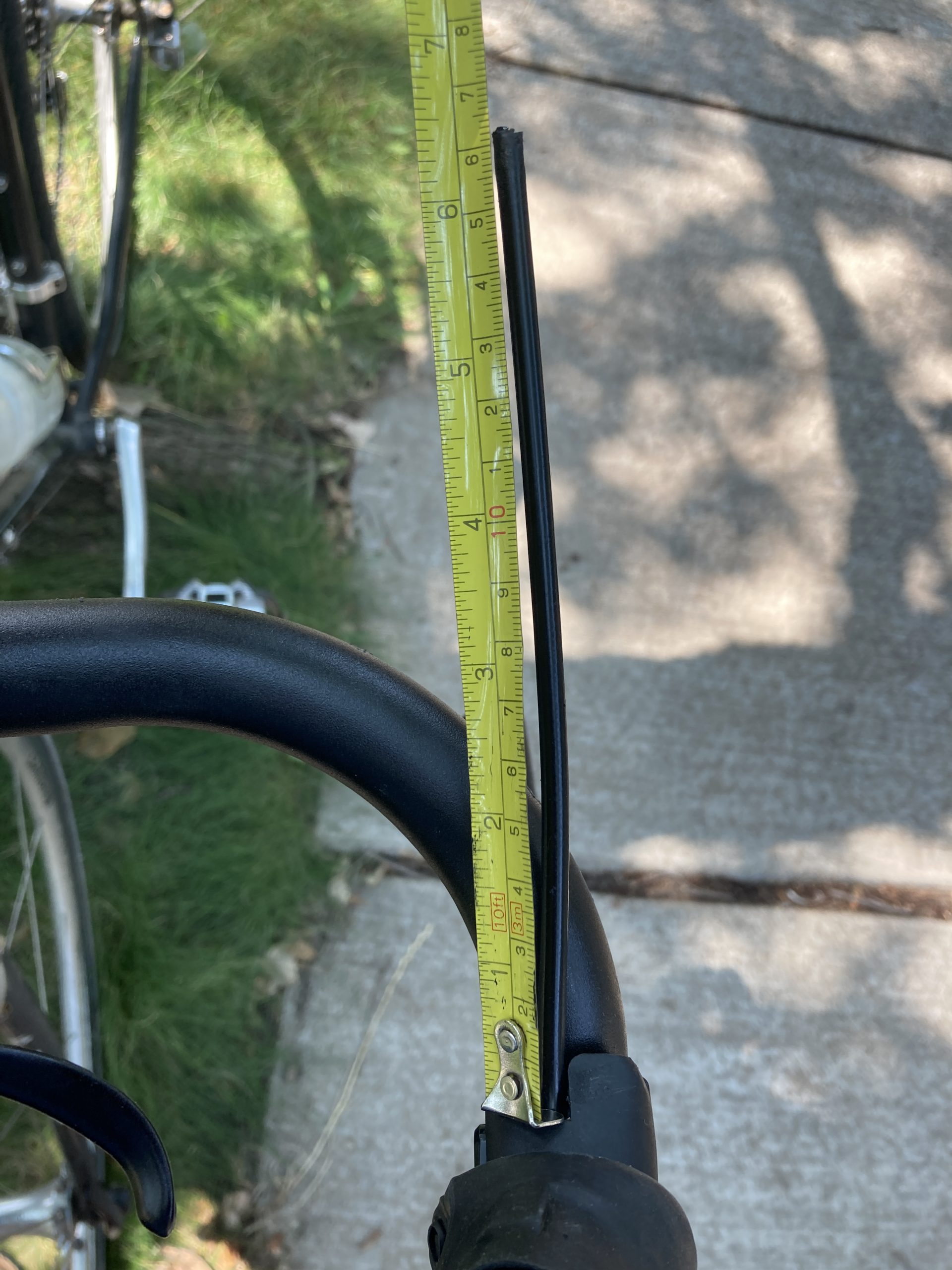
Another thing to know is that there are several sizes of cross levers for several sizes of handlebars. Tektro offers sizes in 24mm, 26mm, and 31.8mm. My handlebars from the original Cross Check complete spec are 26mm at the stem, then taper down to 24mm. After removing the bar tape, you can see this is the farthest inward I could place the levers:
If I wanted to go closer to the stem I would have had to purchase the 26mm version – just be aware of what your setup is before purchasing levers.
You’ll need to cut your brake cable housing. After removing your bar tape, pull out the brake cables. Keep in mind that you might need to replace your brake cable(s) if they’re frayed. Figure out where you want to cut your cable to put the new levers in-line – remember to measure twice and cut once! I cut my brake cable housing 65mm from the brake hoods.
Brake Cable & Housing Tools & Tips
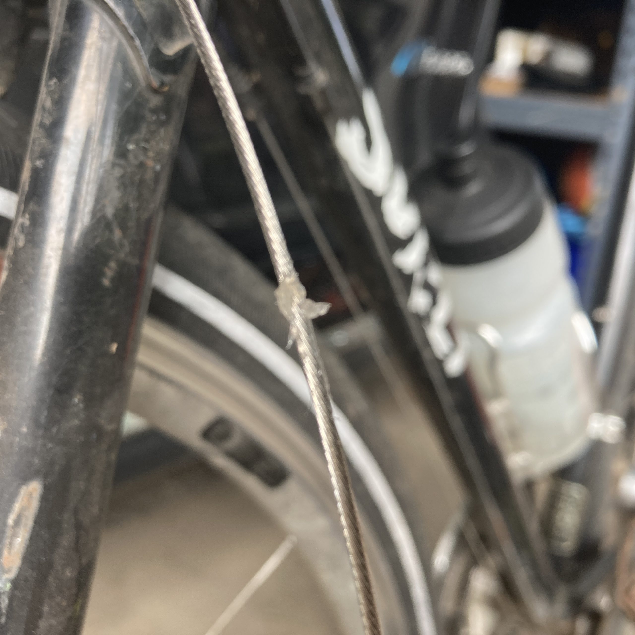
I cut my brake cable housing with a standard side cutter and as you can see above, the cut was rough at best. Then when I went to thread my front brake cable back in, it split and frayed 😩
So I went to the bike shop and bought a new front brake cable and a Park Tool CN-10 Cable/Housing cutter. I noticed on the new brake cable that the manufacturer spot-welds the end to make sure it won’t fray:
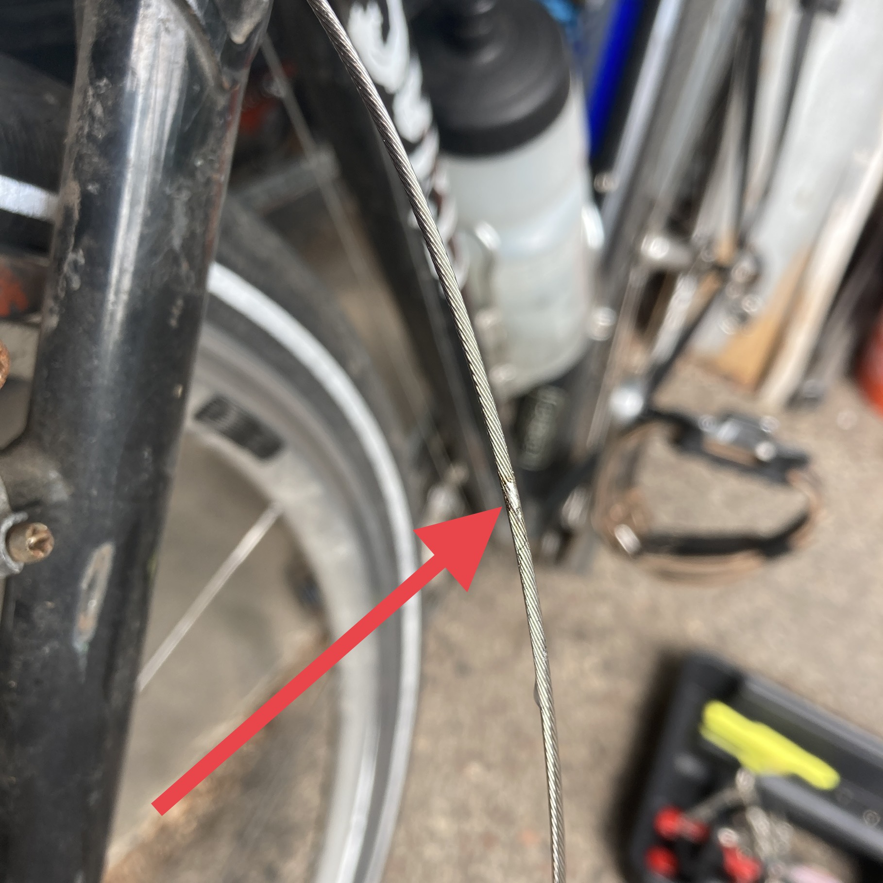
I thought to myself, why not do something similar at home before cutting the cable so it won’t fray? I decided to try and solder the cable with my TS-100 soldering iron. Apparently this is not a new or novel idea 😎 I started by applying some flux to the place I wanted to cut:
Then I added enough solder to soak into the cable and create a “solid” section:
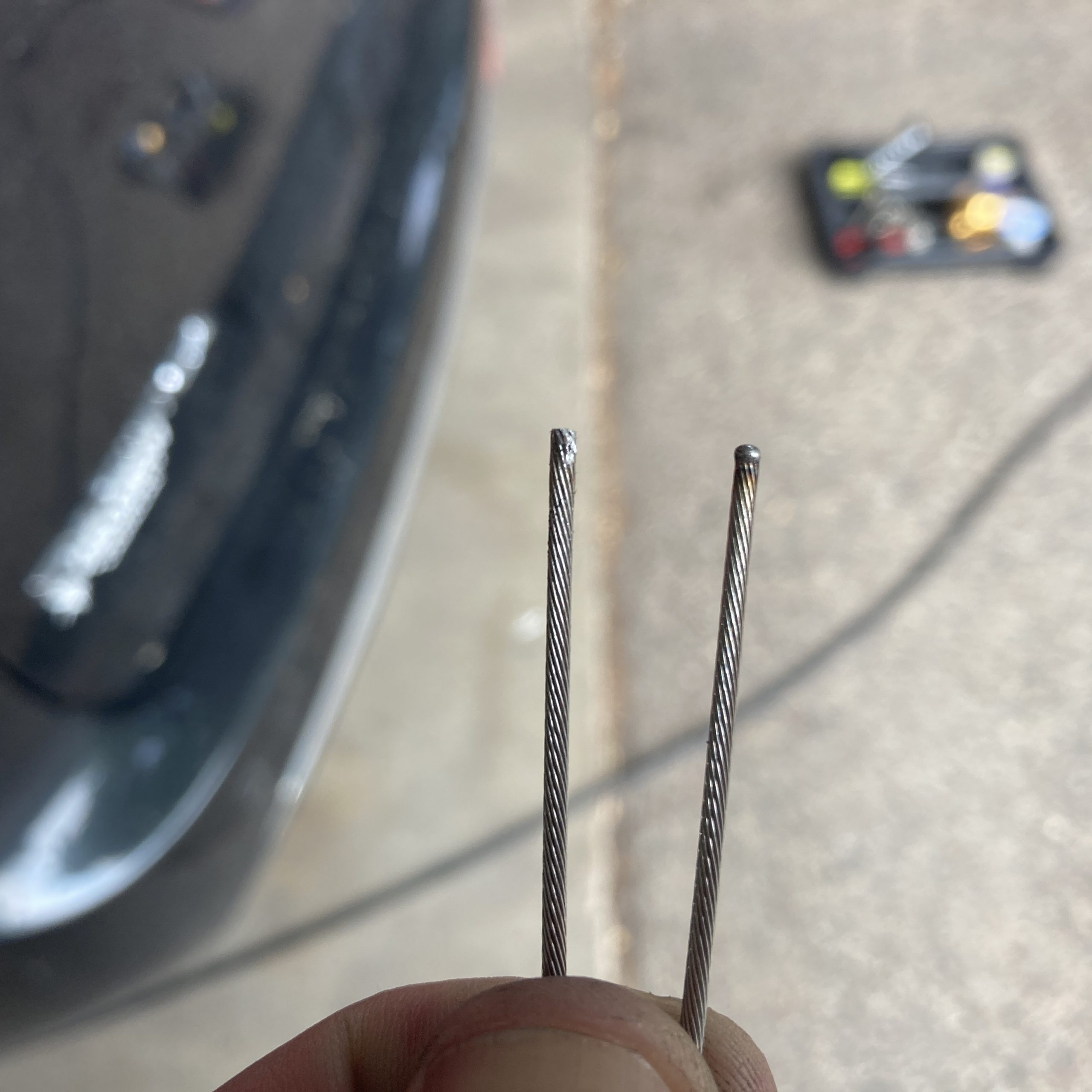
I cut it and it turned out pretty good. In the image below you can compare the soldered section (left) with the original spot-welded section (right).
Bar Tape
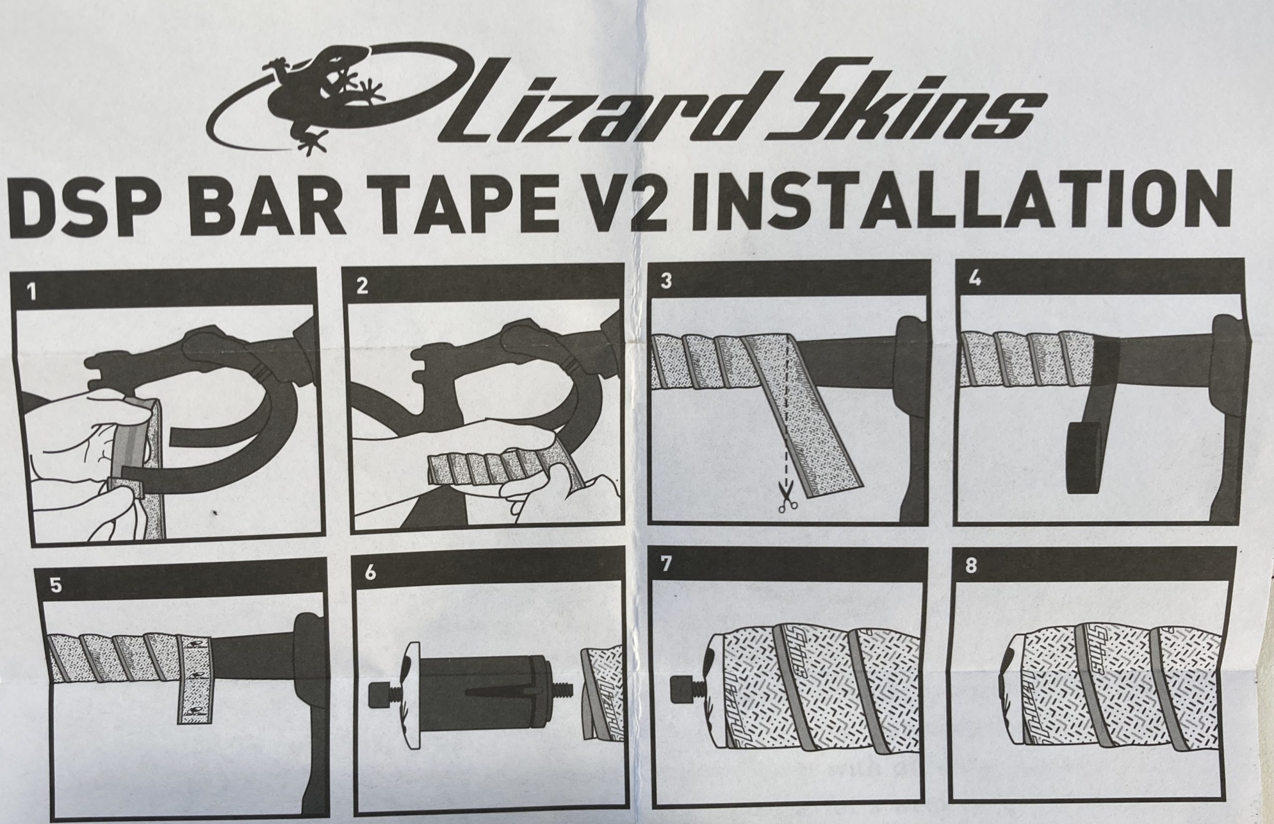
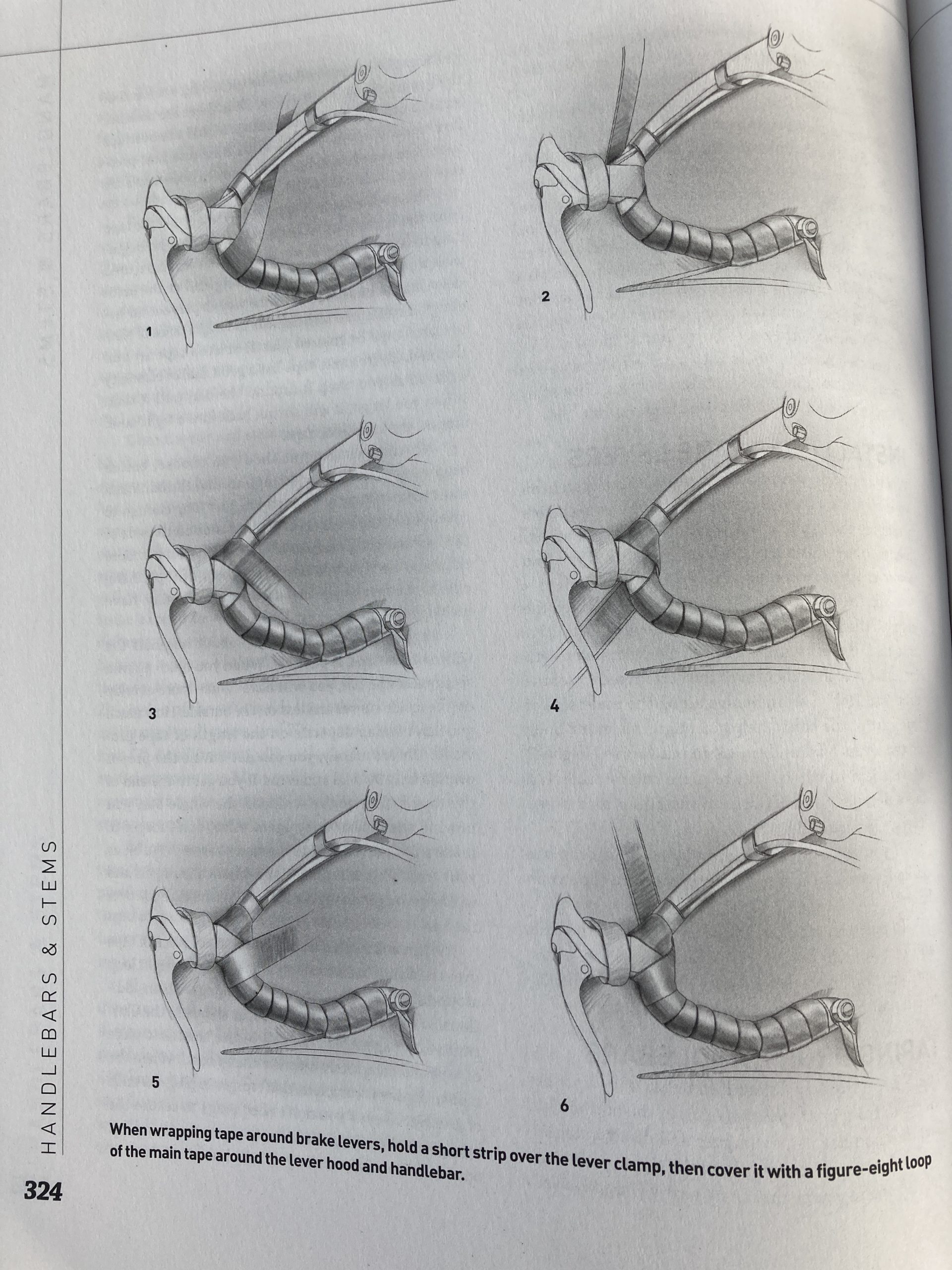
If you’re anything like me I suggest setting aside a couple hours for this project as you’ll be wrapping (and re-wrapping) your bars to get it just right. Two reference materials I kept close at hand were the Lizard Skins instruction diagram:
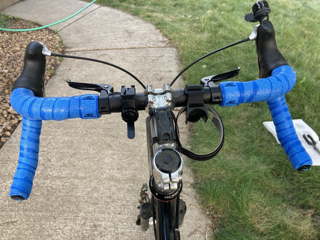
You can see I kept this diagram open (in the grass) to reference as I was taping the bars.
You can also see in that photo that I wrapped the right side wrong coming off the main brakes.
That mistake may have cost me $40 in handlebar tape 😩 I only wrap my bars once every 5 years or so. Next time I might practice with a strip of paper and memorize that figure 8 pattern.
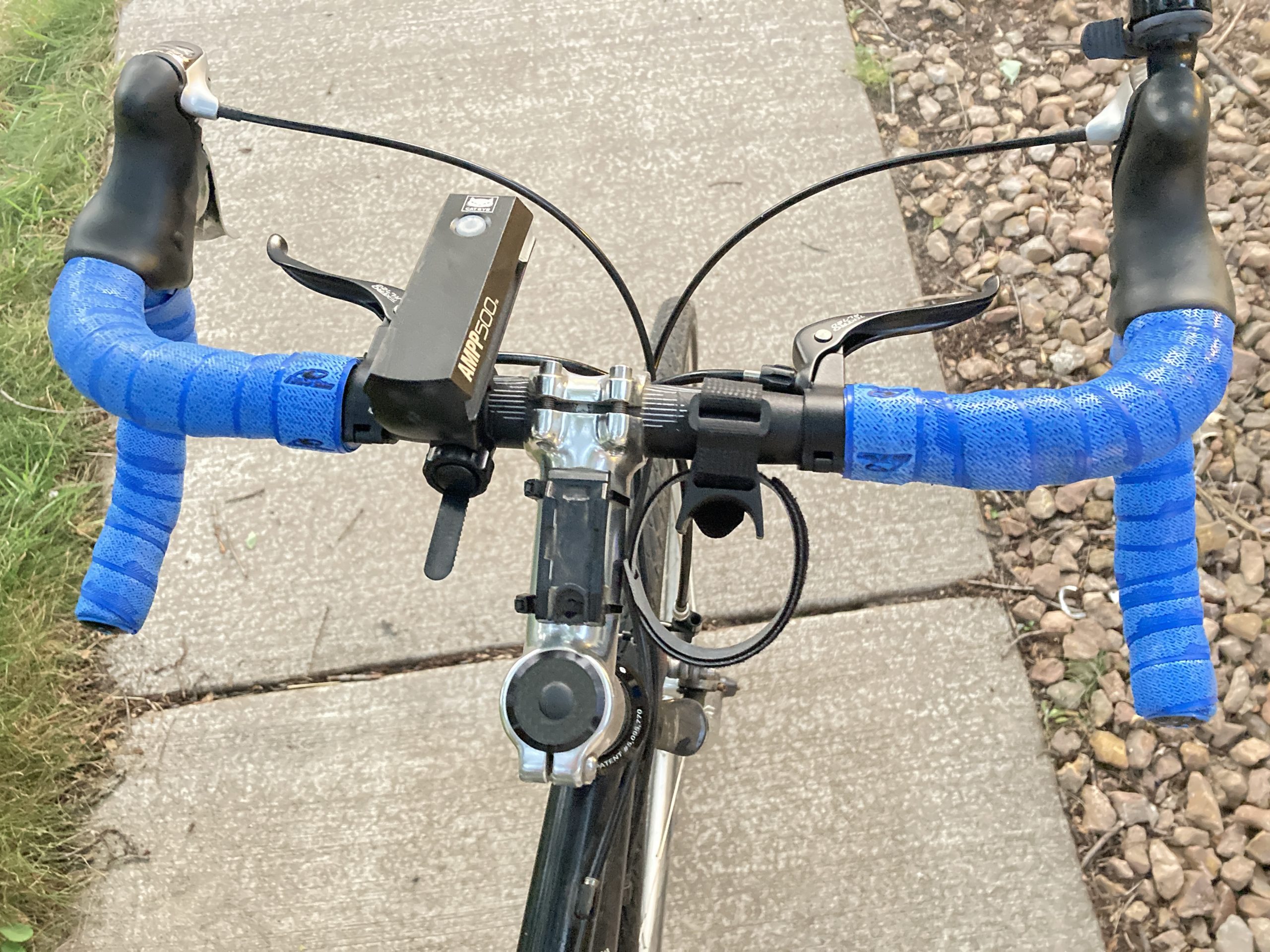
I did manage to undo and redo it correctly. Notice the tape angles are all symmetrical. We’ll see if it holds 🤞
Post-Ride Verdict
The top levers work great – I don’t have to frantically move my hands from the tops to the hoods if I need to brake quickly.
I like the bar tape so far, the best part is Lizard Skins come with screw-tighten bar ends. My old Cinelli bar tape had press-in ends that would fall out on occasion.
When I was getting back into R/C for the 2nd time, circa 2003, I made a conscious choice between getting an HPI Super Nitro Rally and the HPI RS4 (electric) Rally. The music of 18,000 RPMs sounded like a ton of fun, but in the back of my head, it just wasn’t worth it. Smelling like nitro fuel, tuning the engine for the weather, proper maintenance and storage were just a few reasons. Plus all my previousexperience was electric.
At the end of 2020 I donated my Subaru WRX to Newgate School. It was feeling its age and had several gremlins that I didn’t want to deal with: a fuel filler neck that wouldn’t refuel at full speed, an undiagnosed misfire on cylinder #1, and a slipping clutch. Like my decision to bypass nitro, the time was right to give up the rumbly EJ motor sound for the whir of a 200HP electric motor.
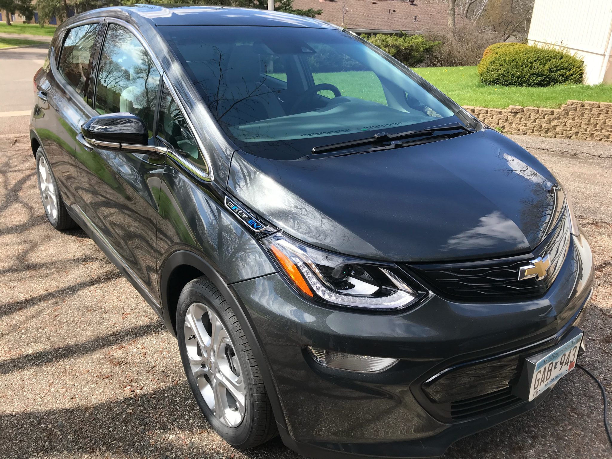
Introducing the official Meatball Racing vehicle: Chevy Bolt
Continue reading →
Our family did our first post-COVID airplane trip to Salt Lake City, Utah. We were there for a week, so I looked up Intermountain RC Raceway (IRCR) – a place I had visited before but never raced at. Their off-road club racing is Wednesday night, so I got the B6 ready to hit the clay.
It was also the first airplane trip that I wanted to bring my RC car on. Normally on road trips it’s a no-brainer. This would be a learning experience – hopefully you can learn from my (many) mistakes.
I could (and probably should) have just packed my car to travel on the airplane as it was only $30 per checked bag – I thought it was going to be $50. Instead I mailed my car to a relative at our destination for $40. If you’re looking for a good video on packing your car for air travel, check this one out by Team Associated:
Continue reading →
Before LED lights were popular, my house had mostly CFL (compact fluorescent lamp) bulbs. One thing I liked about CFL bulbs was the warm-up time, they’d come on a little low and get brighter as they warmed up. This was especially welcome for any late night bathroom trips.
For the garage door opener, I did something different. I installed a “fancy” GE CFL bulb that had an instant-on feature. Here’s an example dual halogen/CFL setup. I don’t remember if my bulb was a hybrid, or if the ballast would just overdrive the bulb to achieve full brightness right away, then back down as the bulb warmed up. 💡
It worked OK, but I noticed my garage light wasn’t staying on for the couple minutes it was supposed to. Finally, in 2021, I got tired of 20 seconds of light in the garage and thought to change the bulb to see if my fancy one didn’t agree with with our Craftsman 3/4HP opener.
The next day I noticed something. The garage door wouldn’t close using the keypad remote. Hmmm.. I had never changed the battery in it, so maybe that was it? It didn’t help.
Maybe I needed to put the opener into learning mode again to pair the keypad after I changed the battery? While I was re-programming the remote, things seemed a bit fussy. Finally I got it to pair. I went up to the opener and noticed the antenna was hanging down when it wasn’t previously. I moved the antenna and then things seemed to start working again. Was my antenna loose? Was I going to have to replace it? 🤔
Then I recall bumping into one of the door sensors while I was reorganizing the garage (which is when I decided to replace the bulbs). There were some cobwebs, so I cleaned them off and made sure the alignment was good.
In the past I’ve occasionally had problems with the door sensors when sunlight shines directly on one of the sensors which blinds it from seeing the actual signal. I thought maybe sunlight had something to do with it because the door always seemed to open, but not shut.
Was it that simple? Was radio interference causing my issue? The antenna is right next to the bulb. I unscrewed the one bulb near the antenna – just enough to turn it off. And then everything worked. 💪
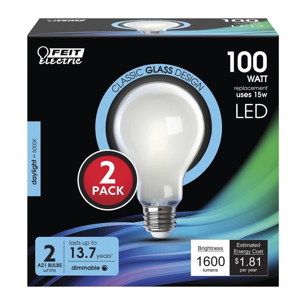
For the record I originally was using these FEIT Electric 100W bulbs:
These are nice bulbs, but they caused radio interference with my Craftsman garage door opener.
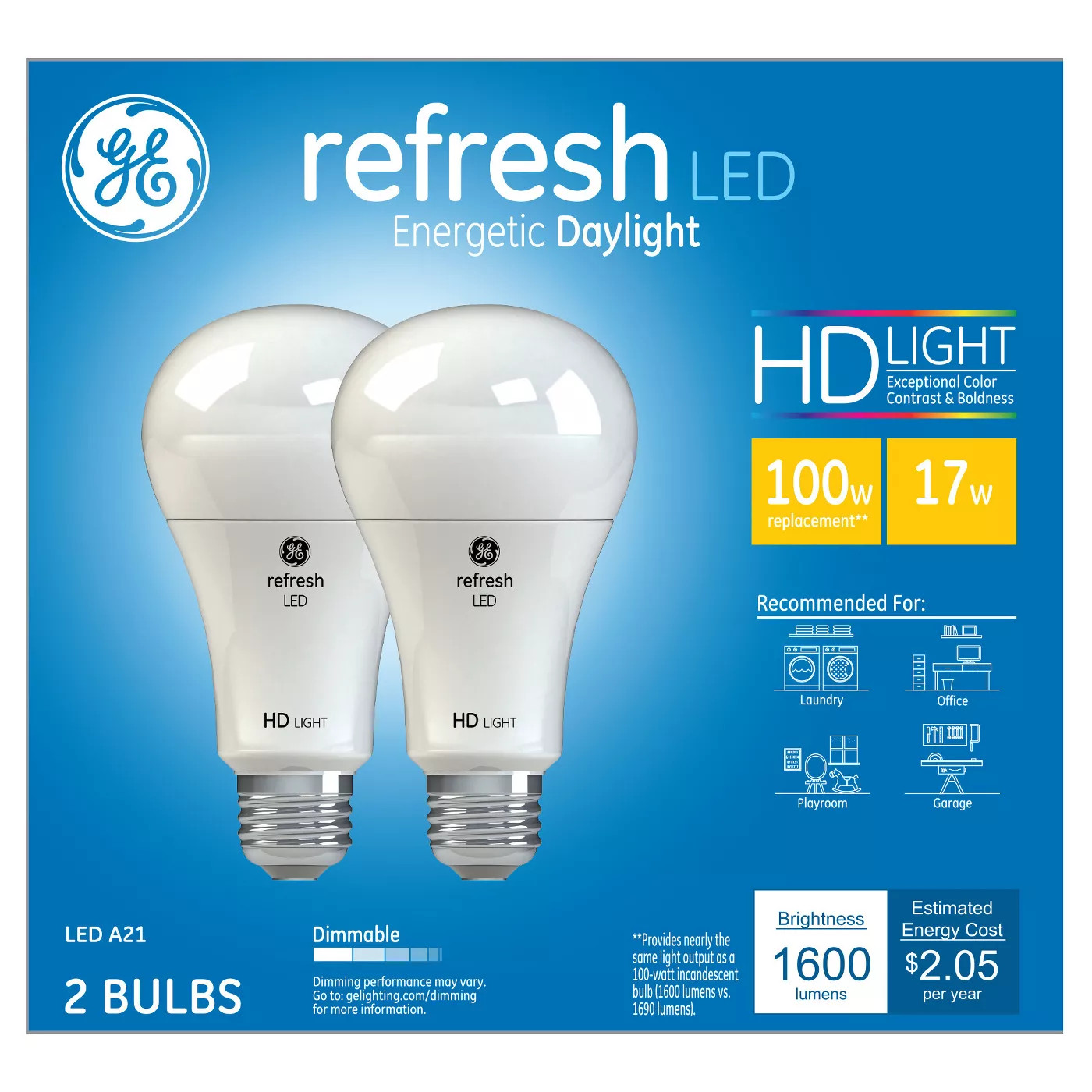
I wanted a working garage door opener and working garage door lights. So I went back to the store and bought a set of General Electric 100W LED bulbs:
These work – I can open the garage and close it! The lights stay on for the prescribed amount of time. Even though both brands of bulbs have the same FCC messaging on the box, in this case it paid to go with the bigger brand name.
Weird to think that this was the cause the whole time – it was hard to wrap my brain around it. The garage would open because at that time the lights are off. When the door opens the lights stay on for a couple minutes and come on again if the door sensor is tripped. When the lights were on, there was enough radio interference (right next to the receiver antenna) to block the signal.
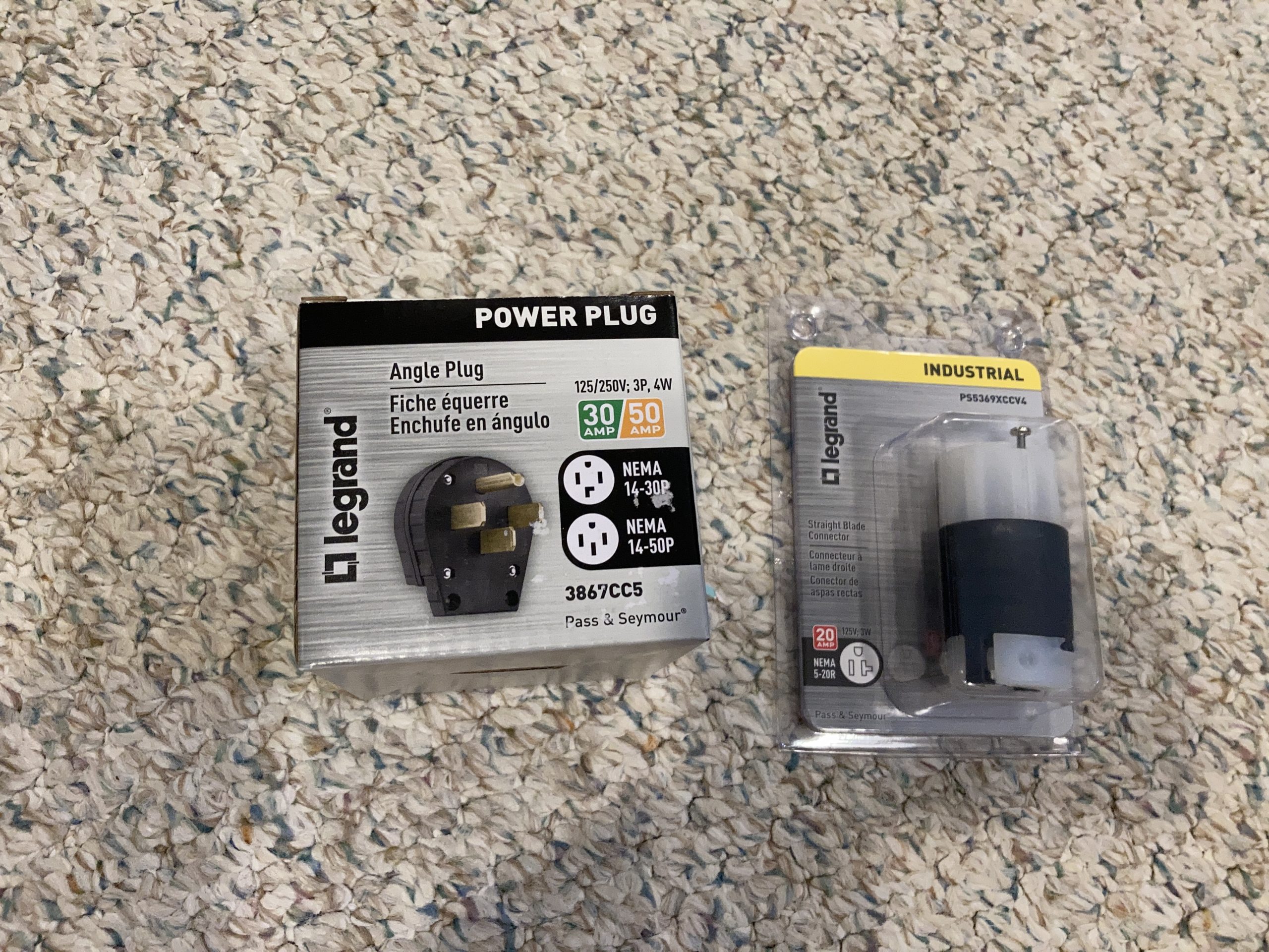
We recently got a 240V outlet installed in the garage so we could buy a Level 2 charger, so I decided to make an adapter to test it out. The adapter instructions from the Bolt site recommends 14 gauge wire or bigger. I had some 12 gauge wire leftover from another project so I used that. All I needed to buy were the plug ends. I got a convertible 14-50 / 14-30 power plug and a female 5-20 end.
Pro-tip:
If you’re starting from scratch and don’t have 14+ gauge electrical cable laying around, you could just pilfer a short 14+ gauge extension cord.
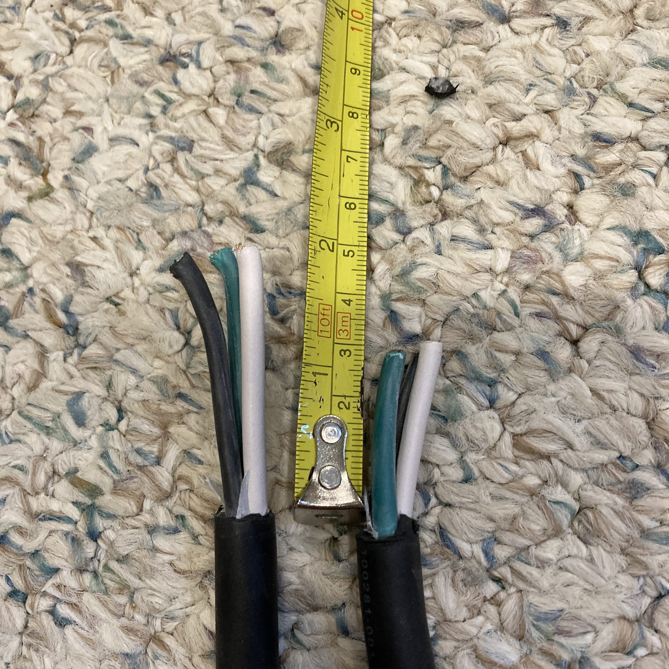
I carefully cut the outer sheath off of the cable and left about 2″ of wire for the 240V plug and 1″ for the “normal outlet” side.
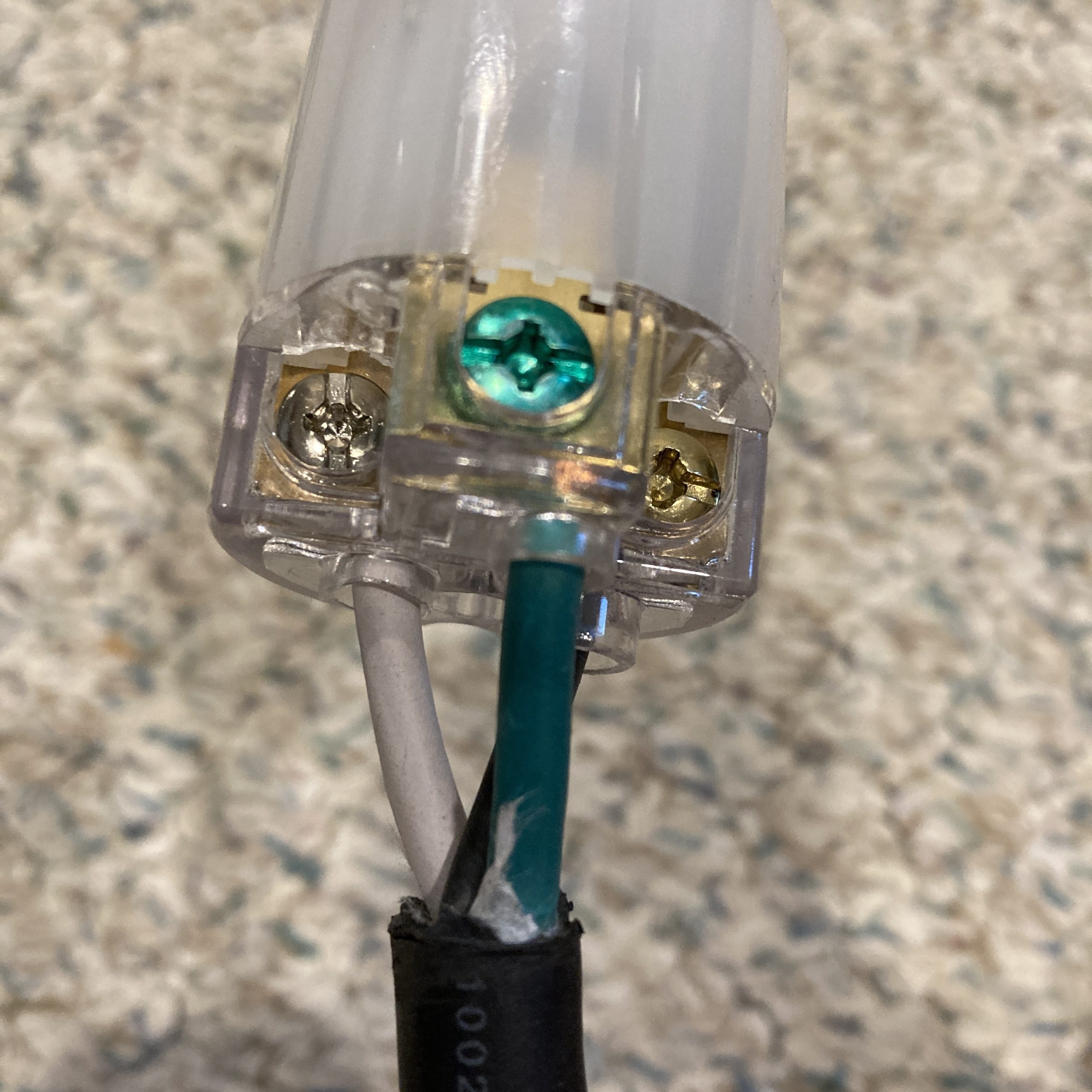
Normal Outlet Side
I stripped the ends of the wires and wired up the normal outlet side first. Green is ground. White goes to the larger port of the outlet, indicated here with a silver screw. Black goes to the narrower outlet blade, indicated with a brass screw.
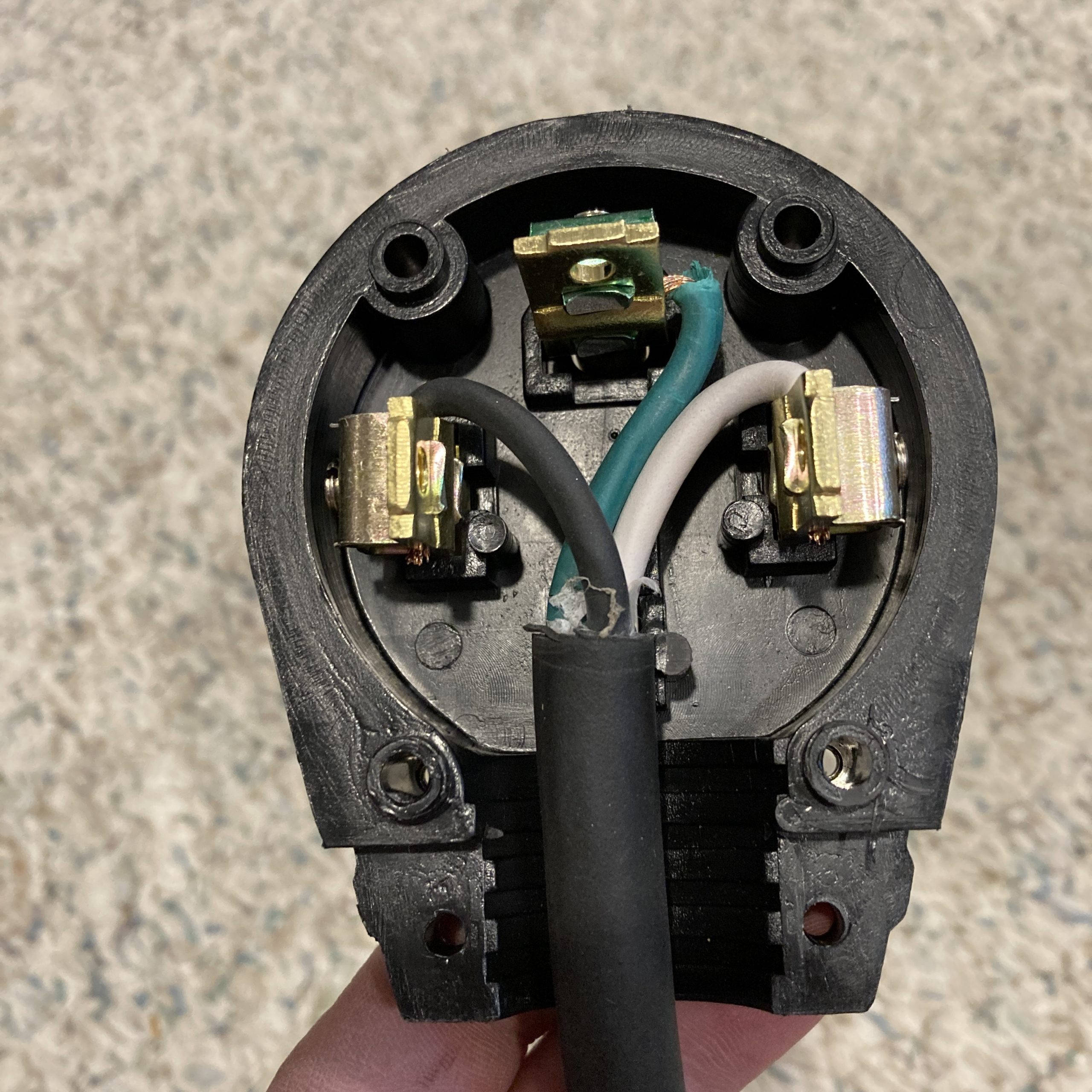
240V Plug
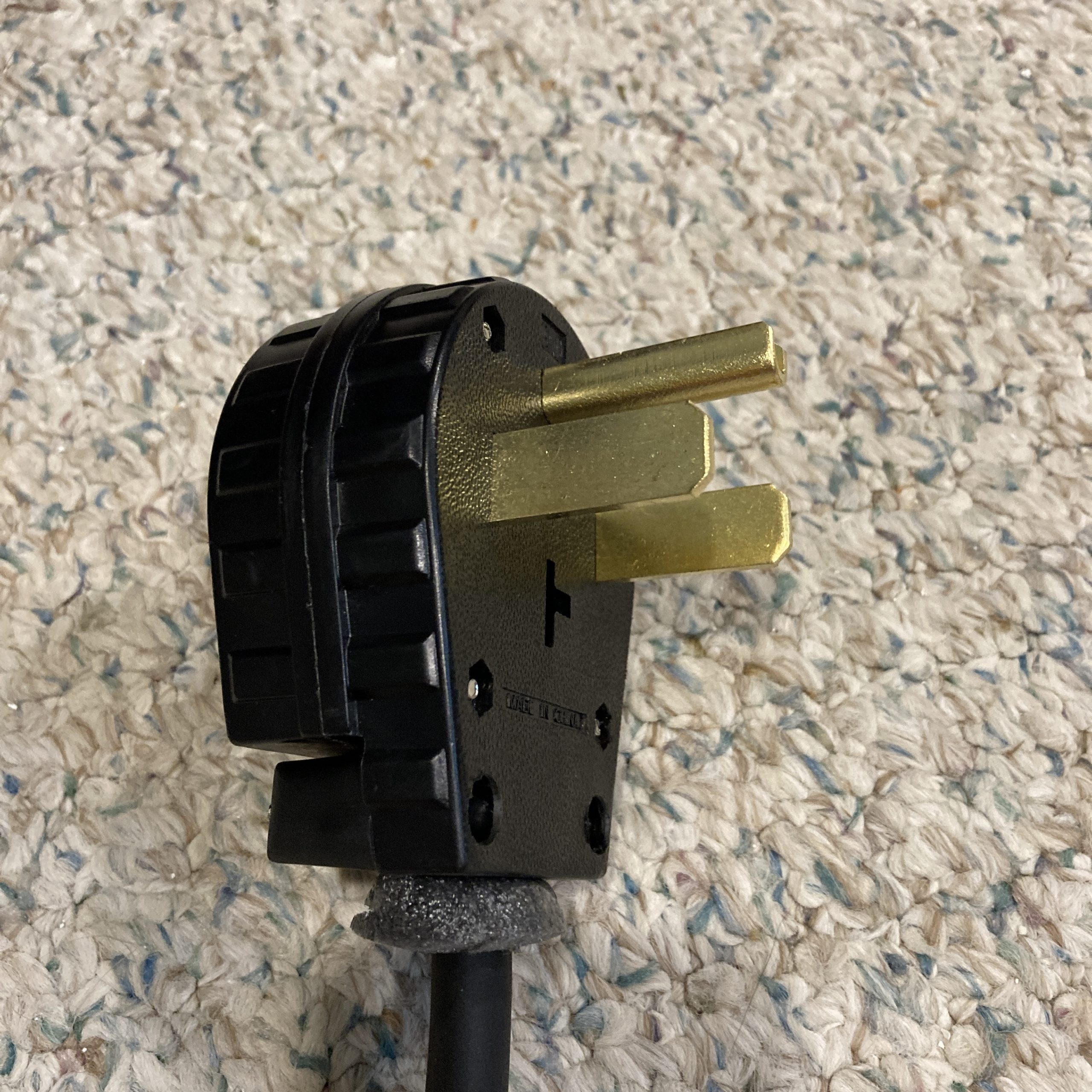
I removed the bottom pin that is used to differentiate the 14-50 (50-amp) and 14-30 (30 amp) plugs. This gives maximum compatibility to use at a 30 or 50-amp outlet. The mopar charger will only draw 12 amps, so it’s safe to use with either style outlet.
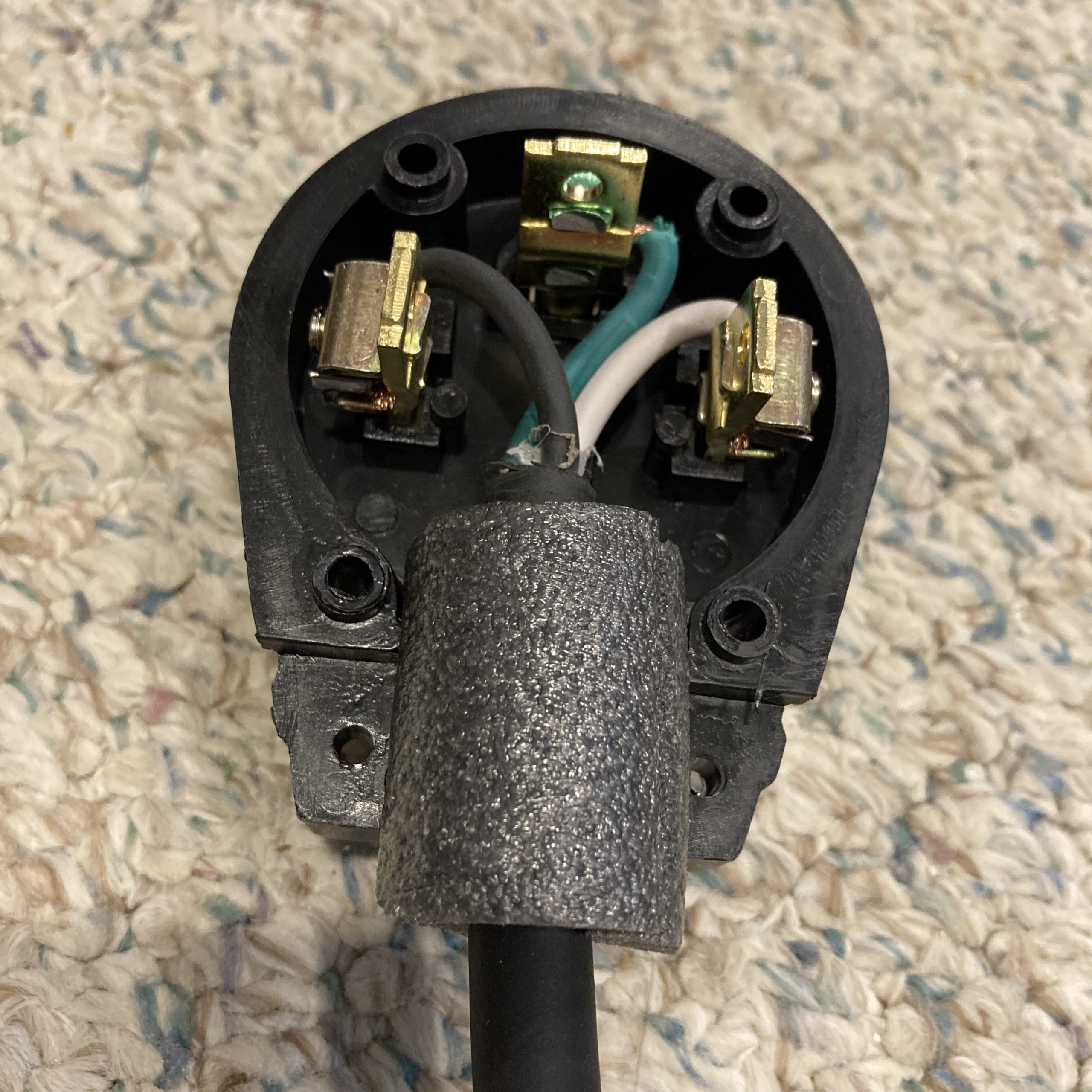
I wired up the 240V plug starting with green for ground. Black goes clockwise from ground if you’re looking at the prongs (CCW when you’re looking from the back as shown here). White goes on the other side.
Because the 240V plug is made to have thick wires coming out for a big 50-amp draw, the comparatively thin 12-gauge wire just dangles loose coming out of the plug. To provide some actual strain relief for the wires, I used some pipe insulation foam that I had laying around from another project. I cut it to fit the wire diameter and used CA glue to affix it to the wire sheath.
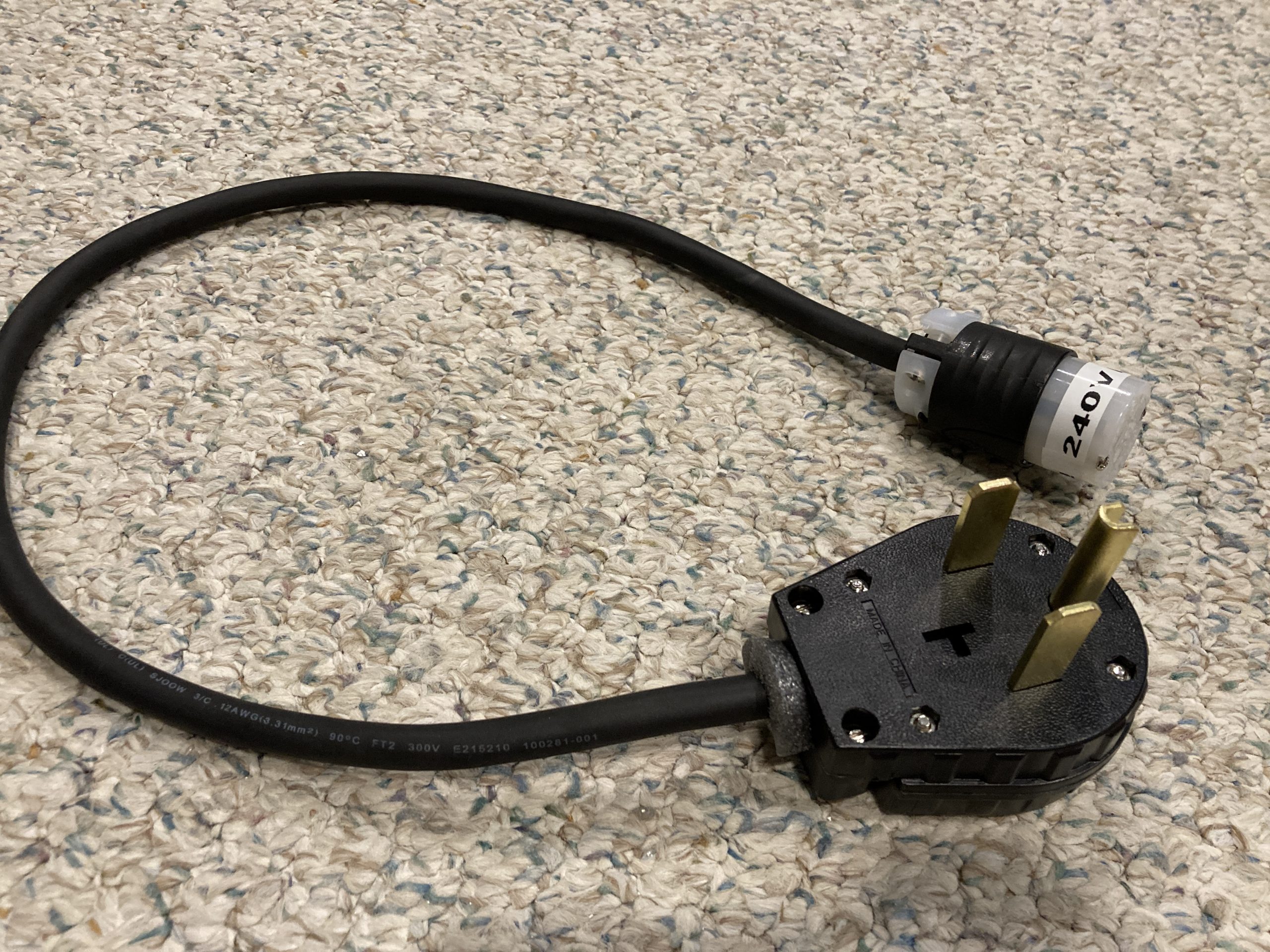
Now when I fasten down the strain relief bridge, it actually grips the foam and wire.
This last bit is optional, but extremely important. I put a label on the plug that says 240V EV ONLY! Just so no one tries to plug something else in and winds up letting out the magic smoke.
Testing
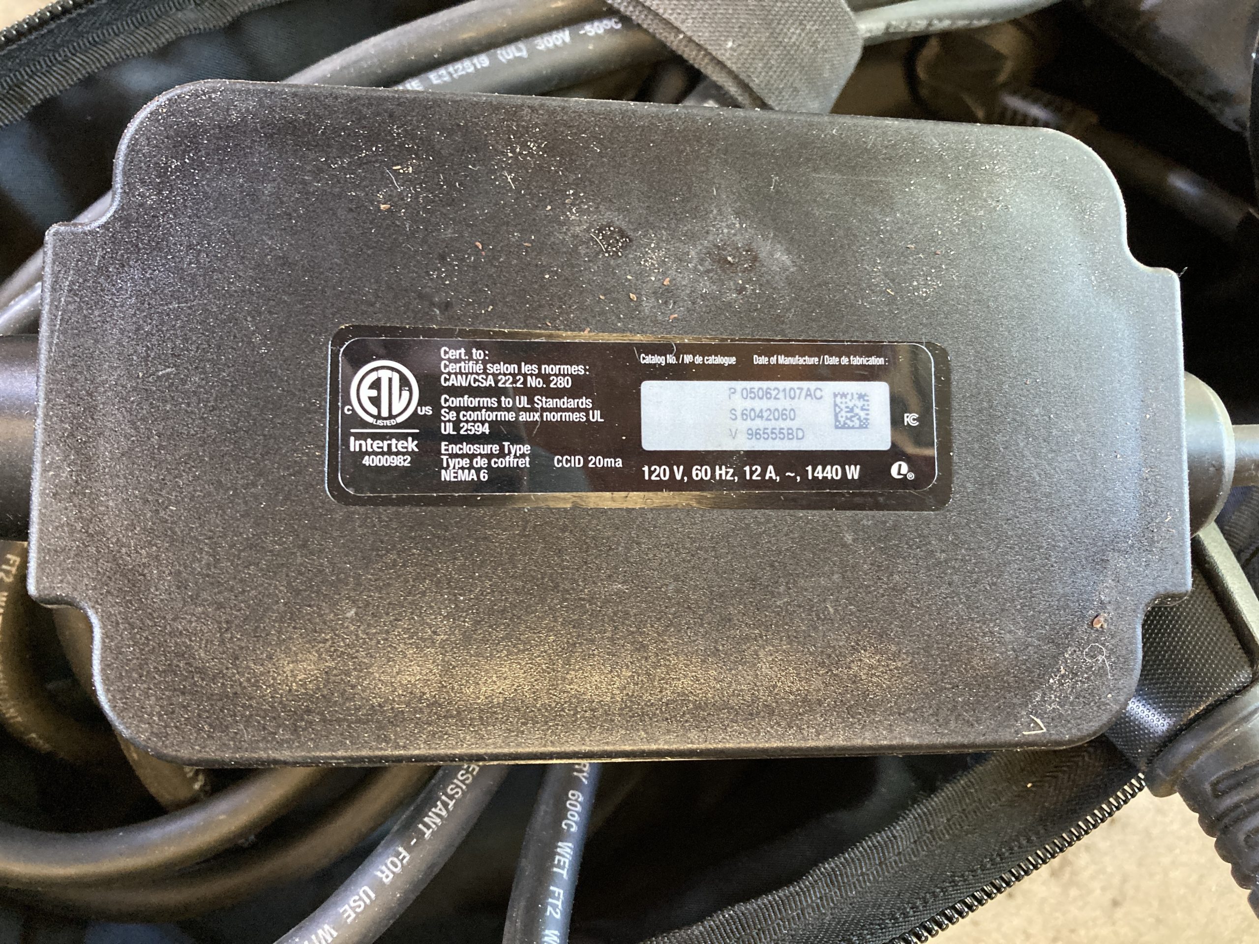
Even though it was stated from another PacHy owner that it works, I was still nervous trying it out as the included charger only indicates 120V – and it’s $350 to replace from the dealer.
An EV owner that lives nearby me remarked that the Level 1 and Level 2 chargers are really just fancy extension cords – the charging circuitry is located in the vehicle itself. So I crossed my fingers 🤞 plugged it in, and got all green lights on the charger.
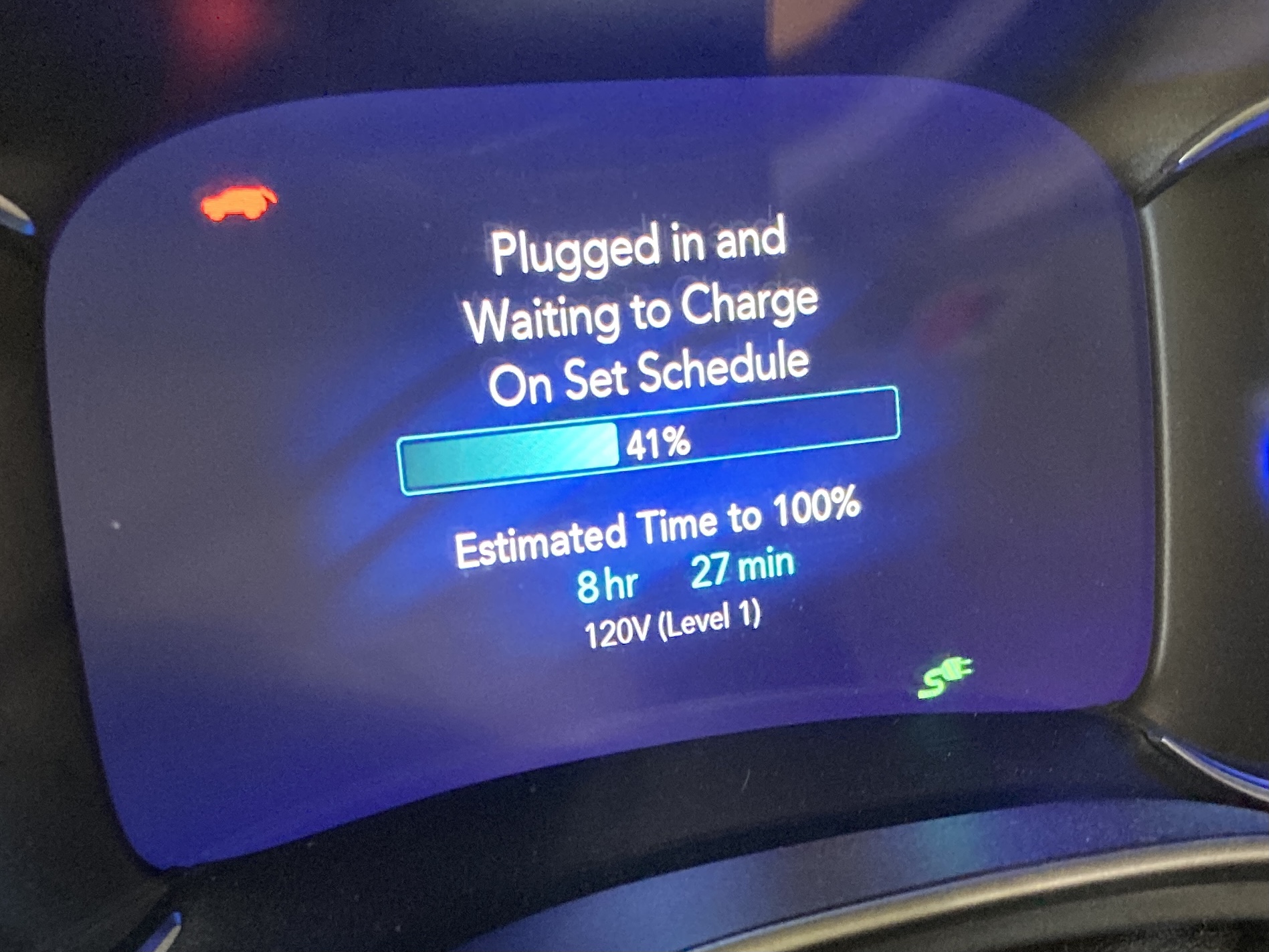
Then, I plugged the charger back into 120V power to do some testing. With 41% charge it was going to take 8 1/2 hours to charge using the normal wall receptacle.
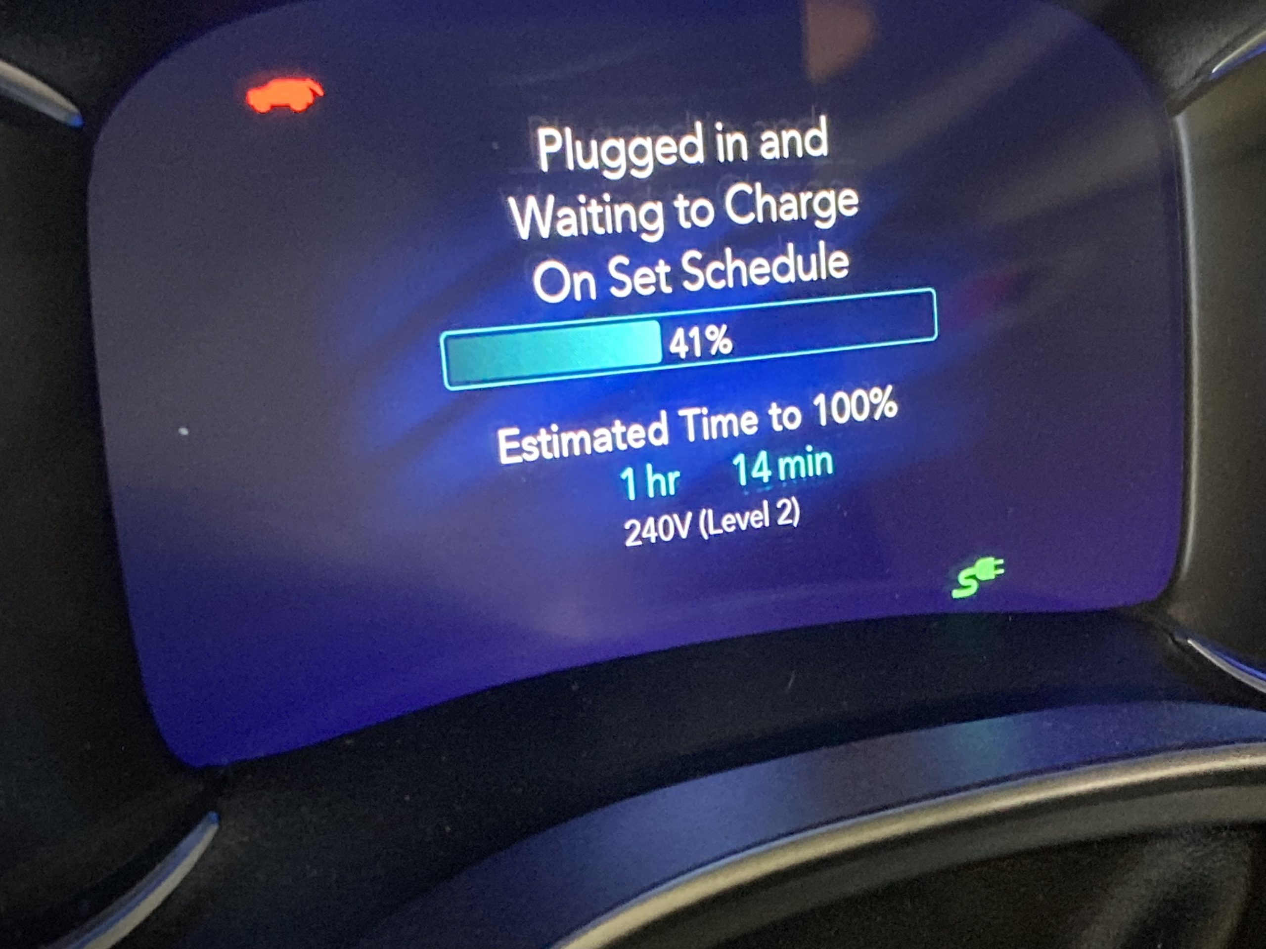
When I plugged it into 240V power, the van thinks it’s hooked up to a full Level 2 charger because it sees the high voltage, but hadn’t drawn any amps. This was because I set the van to charge from 9PM-9AM during off-peak times.
Pro-tip: if you want to skip the charging schedule and charge immediately can you do a double plug. Plug the charger into the vehicle and then unplug immediately, then plug it back in within 10 seconds.
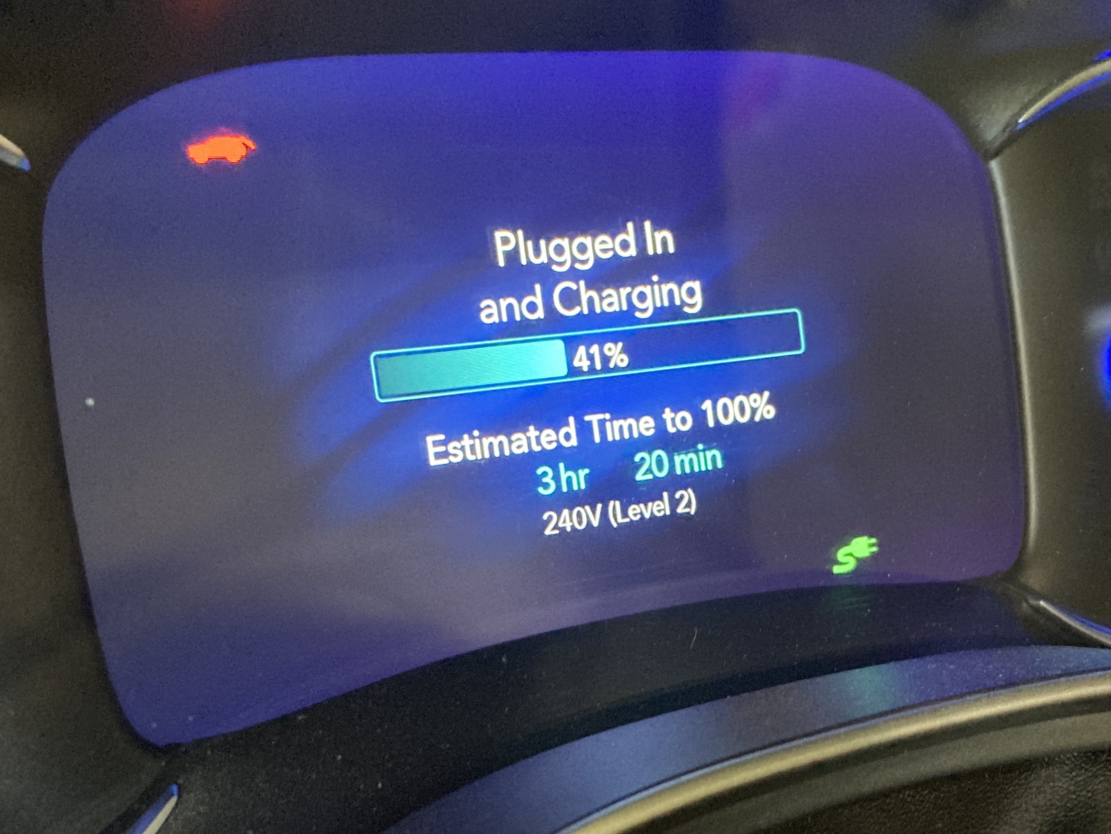
Once the van was actually charging and drawing amps, it updated the charge time and settled in at 3 1/2 hours.
Verdict
Not bad at all! Switching to 240V doesn’t get you a full charge in 2 hours like a 30-amp Level 2 charger will, but I estimate it could do a full charge in less than 6 hours.
I said it before, the 30-mile electric range doesn’t necessitate a Level-2 charger at home because it can do a full charge on 120V in 12 hours overnight. But this is an incredibly cheap way to double your charge rate if you have a 240V outlet available. It’s also a great portable solution if you find yourself somewhere with an RV-style outlet – like a campground ⛺
It cost me less than $30 to make! If you’re thinking about a Level 2 charger and don’t want to shell out a bunch of cash for an electrician to install a 240V outlet and spend a bunch on a Level 2 charger itself – this is a great bridge. Call the electrician first and make this cable. You’ll be ready for Level 2 and can charge fast(er) in the meanwhile ⚡
